

 Image 1 of 1
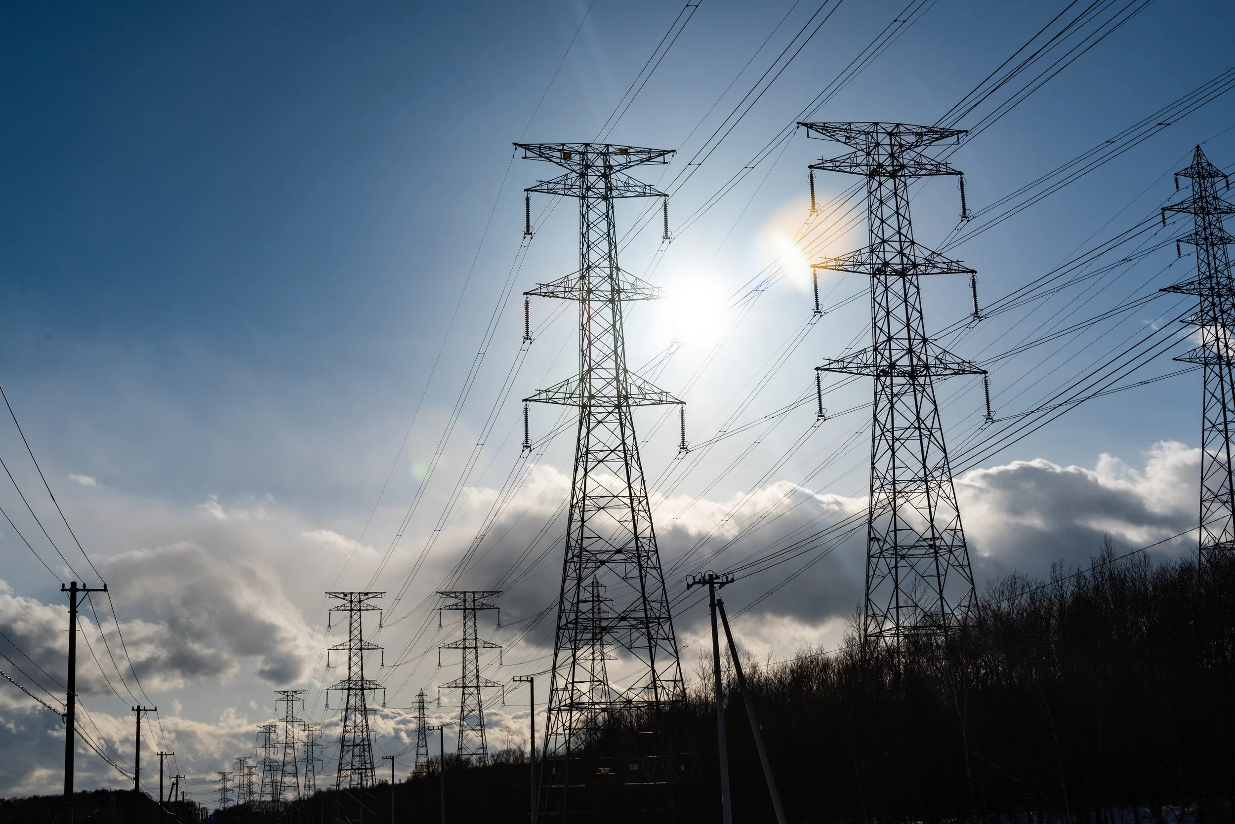
Transmission Towers
Transmission Towers Manufacturer UAE | High-Voltage Power Line Towers
ComTech Steel Industries manufactures robust transmission towers designed for high-voltage electrical power transmission across long distances. Our towers support the reliable transfer of electricity from power generation facilities to distribution networks throughout the UAE and GCC region.
Transmission Towers Overview
Transmission towers are large lattice structures engineered to carry high-voltage conductors over significant spans between power generation sources and distribution substations. These critical infrastructure components must withstand mechanical loads from conductors, environmental forces, and maintain operational reliability for decades.
Our transmission towers are designed using advanced structural analysis and manufactured to meet strict utility specifications and international power infrastructure standards.
Design & Engineering Features
ComTech Steel Industries transmission towers incorporate power infrastructure engineering:
Height Range: 20 meters to 70 meters
Voltage Classes: 66kV to 400kV and higher
Configuration: Suspension, tension, angle, or dead-end types
Conductor Capacity: Single or multiple circuit configurations
Span Capability: Up to 600 meters between towers
Foundation Types: Individual pier or grillage foundations
Climbing System: Internal or external ladder access
Insulator Support: Crossarms and insulator strings
Grounding: Comprehensive earth wire and grounding systems
Wind & Ice Loading: Designed for extreme weather conditions
Technical Standards & Compliance
Our transmission towers meet international power infrastructure standards:
IEC 60826: Design criteria for overhead transmission lines
AASHTO LTS-6: Structural design standards
IEEE Standards: Electrical transmission line specifications
AWS D1.1: Welding quality requirements
EN 1461: Hot-dip galvanization specifications
National Grid Codes: Utility-specific requirements
Service Life: 50-80 years minimum
Tower Types & Configurations
Multiple designs for different transmission line applications:
Suspension Towers
Function: Support conductors along straight line sections
Configuration: Vertical conductor suspension
Usage: Majority of towers in transmission line
Angle Capability: Up to 3 degrees line deviation
Load Type: Primarily vertical conductor loads
Applications: Standard transmission line routing
Tension Towers
Function: Handle conductor tensions at angle points
Configuration: Horizontal conductor pull-off
Usage: Line angle locations
Angle Capability: 3 to 60 degrees line deviation
Load Type: Combined vertical and horizontal loads
Applications: Line direction changes, terrain following
Angle Towers
Function: Large angle line direction changes
Configuration: Heavy-duty tension support
Usage: Major line angles
Angle Capability: 30 to 90 degrees line deviation
Load Type: High horizontal loads
Applications: Significant route changes, corners
Dead-End Towers
Function: Terminate line sections
Configuration: Full conductor termination
Usage: Line ends, section breaks
Angle Capability: Up to 90 degrees
Load Type: Maximum conductor tensions
Applications: Substations, sectioning points
Manufacturing Process
Transmission towers undergo heavy-duty manufacturing:
Engineering Design: Load analysis per utility specifications
Structural Calculations: Member sizing and connection design
Fabrication Drawings: Detailed member and assembly drawings
Member Fabrication: Angle section cutting and preparation
Assembly Operations: Tower section assembly
Bolt Holes: Precision hole punching or drilling
Welding: AWS D1.1 compliant welded connections
Hot-Dip Galvanization: Complete immersion coating
Quality Control: Dimensional and coating inspection
Packing: Systematic bundling for transport and erection
Conductor Configurations
Multiple conductor arrangement options:
Single Circuit Towers
One Three-Phase Circuit: Single voltage level
Crossarm Configuration: Horizontal or delta arrangement
Conductor Spacing: Optimized for voltage class
Ground Wires: One or two overhead ground wires
Applications: Standard transmission lines
Double Circuit Towers
Two Three-Phase Circuits: Increased power transfer
Vertical Stacking: Upper and lower circuit levels
Independent Operation: Redundancy for reliability
Space Efficiency: Single right-of-way corridor
Applications: High-capacity transmission corridors
Customization Options
Full customization for utility requirements:
Custom Heights: Based on terrain and conductor clearance
Voltage Class: 66kV to 400kV and higher
Conductor Configuration: Single or double circuit
Foundation Type: Designed for soil conditions
Special Features: Aviation marking, climbing ladders
Crossarm Design: Utility-specific requirements
Grounding System: Enhanced earth electrode systems
Material Grade: High-strength steel for long spans
Applications
Transmission towers are essential for:
Inter-City Transmission: Long-distance power transfer
Generation Connection: Power plant to grid connection
Substation Interconnection: High-voltage grid network
Cross-Border Links: International power exchange
Renewable Energy Evacuation: Solar and wind farm connections
Industrial Supply: High-voltage industrial connections
Grid Reinforcement: Network capacity upgrades
Emergency Interconnections: Grid reliability improvement
Foundation Engineering
Custom foundation design for each tower location:
Geotechnical Investigation: Soil properties determination
Foundation Type: Pier, pad, grillage, or pile foundations
Load Transfer: Tower to ground load distribution
Uplift Resistance: Wind and ice load uplift capacity
Settlement Analysis: Long-term stability verification
Excavation Design: Safe excavation procedures
Construction Drawings: Complete foundation details
Installation & Erection
Specialized transmission tower construction:
Site Access: Construction roads and work areas
Foundation Construction: Concrete work and anchor setting
Tower Assembly: Section-by-section erection
Crane Requirements: Heavy lifting equipment
Helicopter Erection: Remote location deployment option
Quality Assurance: Inspection during construction
Conductor Stringing: Cable installation coordination
Testing & Commissioning: Line energization support