

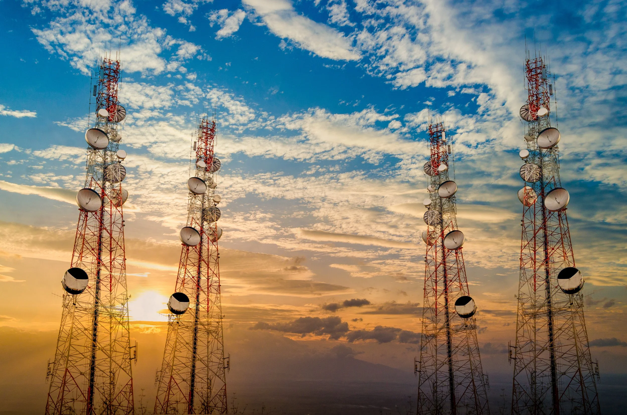
Telecom Infrastructure
ComTech Steel Industries manufactures high-performance steel structures designed to support modern telecom and wireless communication networks.
All telecom infrastructure solutions are fabricated in the UAE and engineered to meet international standards for structural stability, wind resistance, and long-term operational reliability.
Telecom Infrastructure Overview
ComTech Steel Industries provides engineered steel solutions for telecom infrastructure projects supporting 4G, 5G, and wireless communication networks.
Our telecom structures are designed to ensure reliable network coverage, efficient equipment mounting, and long-term performance across urban, suburban, and remote environments.
The category includes space-efficient monopoles, high-capacity telecom towers, and rooftop solutions tailored to site-specific and regulatory requirements.
Design & Engineering
Our telecom infrastructure structures are engineered to meet demanding technical and environmental requirements.
Design considerations include:
Structural configuration (monopole, lattice tower, rooftop mast)
Height ranges and sectioning based on coverage needs
Load calculations for antennas, microwave dishes, and equipment
Wind load, seismic considerations, and environmental exposure
Custom engineering based on site conditions and operator requirements
Each design is optimized for safety, ease of installation, and long-term operational stability.
Technical Standards & Features
All telecom infrastructure products are designed and manufactured in compliance with internationally recognized standards.
Key technical features include:
Structural design in accordance with AASHTO standards
Welding compliant with AWS D1.1
Material standards aligned with EN and BS specifications
High wind resistance suitable for exposed locations
Expected service life of 25–50+ years
Accessories & Optional Components
Telecom infrastructure structures can be supplied with a range of accessories and optional components, including:
Antenna and microwave brackets
Cable trays and ladder systems
Mounting frames and platforms
Anchor bolts and base plate assemblies
Access doors and safety features
All accessories can be customized to match equipment layouts and installation requirements.
Applications & Use Cases
ComTech Steel Industries telecom infrastructure solutions are commonly used in:
Mobile network deployments (4G / 5G)
Urban and suburban coverage expansion
Rural and remote area connectivity
Rooftop and space-constrained installations
Telecom network upgrades and densification projects
Telecom Infrastructure Solutions We Manufacture
Telecom Monopoles Manufacturer UAE | 4G & 5G Network Poles
ComTech Steel Industries manufactures high-performance telecom monopoles designed to support modern 4G and 5G wireless communication networks across the UAE and GCC region. Our monopoles provide space-efficient, aesthetically acceptable solutions for mobile network infrastructure deployment.
Telecom Monopoles Overview
Telecom monopoles are single-shaft steel structures designed to support multiple antennas, RRUs (Remote Radio Units), microwave dishes, and associated telecommunications equipment. These poles offer minimal footprint while providing the structural capacity required for dense antenna installations.
Our telecom monopoles are engineered for quick installation, high equipment capacity, and long-term reliability in all environmental conditions.
Design & Engineering Features
ComTech Steel Industries telecom monopoles incorporate telecommunications engineering:
Height Range: 15 meters to 45 meters
Tapered Design: Optimal strength-to-weight ratio
Multi-Section Construction: 2-5 sections depending on height
Antenna Load Capacity: Engineered for multiple operator sharing
Wind Load Design: Up to 180 km/h for exposed locations
Equipment Platforms: Optional platforms at multiple levels
Cable Management: Internal or external ladder and cable trays
Foundation Design: Custom engineering for soil conditions
Future Expansion: Designed for technology upgrades
Technical Standards & Compliance
Our telecom monopoles meet telecommunications industry standards:
AASHTO LTS-6: Structural design standards
TIA-222-H: Telecommunications structure standards
AWS D1.1: Welding quality specifications
EN 1461: Hot-dip galvanization requirements
IEC Standards: Electrical safety and grounding
Service Life: 30-50 years minimum
Antenna Mounting Solutions
Comprehensive antenna support systems:
Mounting Configurations
Sector Antennas: Triple-sector standard configuration
Omni Antennas: 360-degree coverage installations
Panel Antennas: Multiple operator co-location
Microwave Dishes: Point-to-point backhaul support
Small Cells: 5G densification equipment
RRU Mounting: Integrated radio unit positioning
Mounting Hardware
Antenna Brackets: Adjustable azimuth and tilt
Pipe Mounts: Sector antenna arms
Equipment Shelves: RRU and power system mounting
Cable Management: Ladder systems and cable trays
Grounding System: Complete lightning protection
Future Provisions: Reserved mounting locations
Manufacturing Process
Telecom monopoles undergo telecommunications-grade manufacturing:
Network Engineering: Coverage and capacity planning support
Structural Design: Load analysis including all equipment
Section Fabrication: Precision tapered section manufacturing
Test Assembly: Factory trial assembly for fit verification
Welding Quality: AWS D1.1 certified welding procedures
Hot-Dip Galvanization: Complete corrosion protection
Mounting Hardware: Pre-installation of brackets and fittings
Quality Testing: Dimensional and coating verification
Documentation: Complete as-built drawings and certificates
Customization Options
Full customization for telecommunications requirements:
Custom Heights: Any height from 15m to 45m
Section Configuration: Optimized for transport and installation
Antenna Capacity: Designed for operator requirements
Equipment Platforms: Custom positions and capacities
Cable Management: Internal or external systems
Surface Finish: Galvanized or galvanized + RAL color
Access Provisions: Ladder systems where required
Special Features: Aviation lights, grounding systems
Applications
Telecom monopoles support multiple network applications:
Urban Coverage: City center and residential network deployment
Suburban Networks: Growing area network expansion
Highway Coverage: Transportation corridor connectivity
Industrial Zones: Manufacturing and logistics area networks
5G Densification: High-capacity small cell deployment
Rural Connectivity: Remote area network extension
Network Upgrades: Technology migration projects
Co-Location Sites: Multiple operator infrastructure sharing
Technology Compatibility
Engineered for current and future technologies:
2G/3G Legacy: Support for existing equipment
4G LTE: Current generation network deployment
5G Networks: Sub-6 GHz and mmWave capable
Massive MIMO: High-capacity antenna arrays
Small Cells: Densification equipment integration
Fiber Backhaul: Cable routing provisions
Microwave Links: Point-to-point dish support
IoT Infrastructure: Low-power wide-area network support
Installation & Commissioning
Complete deployment support services:
Site Surveys: Structural and RF engineering assessment
Foundation Design: Soil investigation and design
Crane Requirements: Lifting plan and specifications
Installation Supervision: On-site engineering support
Antenna Installation: RF engineering coordination
System Integration: Equipment mounting and cabling
Testing & Commissioning: Network activation support
Documentation: As-built drawings and certifications
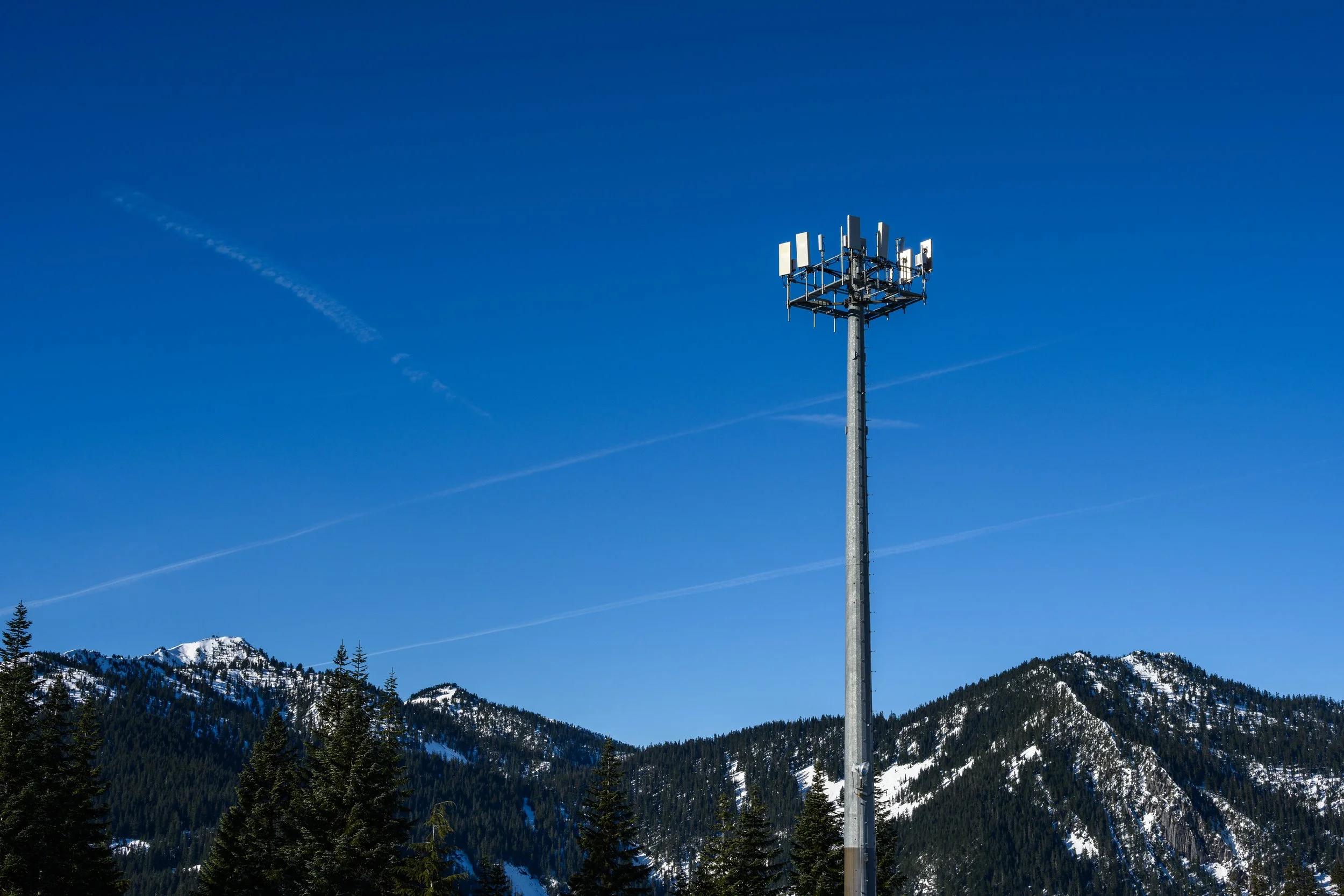
Space-efficient steel monopoles designed to support multiple telecom antennas while minimizing visual impact and land use.

Antenna Monopoles Manufacturer UAE | Specialized Telecom Antenna Poles
ComTech Steel Industries manufactures specialized antenna monopoles engineered specifically for optimal antenna mounting and RF performance. Our antenna monopoles are designed to provide stable, secure platforms for sector antennas, panel antennas, and wireless communication equipment across the UAE and GCC region.
Antenna Monopoles Overview
Antenna monopoles are purpose-built telecommunications structures optimized for antenna installations. Unlike general telecom monopoles, these poles are specifically engineered with mounting provisions, cable routing, and structural characteristics that maximize RF performance and equipment accessibility.
Our antenna monopoles feature precision-engineered mounting points, optimized spacing for antenna separation, and minimal RF interference characteristics essential for high-performance wireless networks.
Design & Engineering Features
ComTech Steel Industries antenna monopoles incorporate RF-optimized engineering:
Height Range: 12 meters to 40 meters
Tapered Profile: Aerodynamic design minimizing wind resistance
Antenna Mounting Zones: Pre-engineered locations for optimal RF performance
Mounting Hardware: Integrated brackets and pipe mounts
Azimuth Adjustability: 360-degree positioning capability
Tilt Mechanisms: Vertical angle adjustment provisions
Equipment Capacity: Designed for multiple antenna arrays
Cable Pathways: Dedicated internal or external cable routes
RRU Integration: Mounting provisions for remote radio units
Lightning Protection: Comprehensive grounding system
Technical Standards & Compliance
Our antenna monopoles meet telecommunications and structural standards:
TIA-222-H: Telecommunications structure standards
AASHTO LTS-6: Structural design compliance
AWS D1.1: Welding quality specifications
EN 1461: Hot-dip galvanization standards
IEC 62305: Lightning protection systems
RF Performance: Minimal interference characteristics
Service Life: 30-50 years minimum
Antenna Configurations Supported
Comprehensive antenna mounting solutions:
Sector Antenna Arrays
Three-Sector Configuration: 120-degree coverage pattern
Six-Sector Configuration: 60-degree high-capacity deployment
Cross-Polarized Arrays: Dual-band installations
Vertical Separation: Optimized spacing for frequency reuse
Horizontal Separation: Interference mitigation
Panel Antenna Systems
Multi-Band Panels: 700 MHz to 2600 MHz support
Massive MIMO Arrays: 5G high-capacity installations
Co-Location Mounting: Multiple operator equipment
Future Expansion: Reserved mounting positions
Equipment Integration: RRU proximity mounting
Specialized Applications
Omni-Directional Antennas: 360-degree coverage
Microwave Backhaul: Point-to-point dish mounting
Small Cell Integration: 5G densification equipment
IoT Gateways: LoRaWAN and NB-IoT installations
Private Networks: Industrial and campus wireless
Manufacturing Process
Antenna monopoles undergo telecommunications-focused manufacturing:
RF Engineering Coordination: Coverage and capacity planning
Structural Analysis: Load calculations including antenna wind loads
Mounting Point Precision: Exact positioning for RF optimization
Section Fabrication: Tapered section manufacturing
Hardware Pre-Installation: Antenna brackets and mounting systems
Cable Management Integration: Internal routing or ladder systems
Hot-Dip Galvanization: Corrosion protection coating
Quality Verification: Dimensional and RF characteristic testing
Technical Documentation: Complete mounting specifications
Customization Options
Full customization for RF and structural requirements:
Custom Heights: 12m to 40m based on coverage requirements
Taper Design: Optimized for antenna separation and wind loads
Mounting Configurations: Single or multi-operator support
Cable Management: Internal conduit or external ladder systems
Surface Finish: Galvanized or RAL color powder coating
Equipment Platforms: Optional working platforms at antenna levels
Grounding System: Enhanced lightning protection
Access Provisions: Climbing ladder or service lift compatibility
Applications
Antenna monopoles are ideal for:
Urban Network Deployment: City center high-capacity sites
Suburban Coverage: Residential area network expansion
Highway Corridors: Transportation route connectivity
Campus Networks: University and corporate facilities
Industrial Complexes: Manufacturing and logistics sites
5G Densification: High-frequency small cell deployment
Private LTE/5G: Industrial IoT and automation networks
Emergency Services: Public safety communication networks
Smart City Infrastructure: Integrated sensor and connectivity nodes
Rural Coverage: Remote area network extension
RF Performance Optimization
Engineering considerations for optimal wireless performance:
Antenna Separation: Calculated spacing to minimize interference
Pattern Optimization: Mounting heights for coverage overlap
Co-Location Spacing: Frequency isolation between operators
Backhaul Integration: Line-of-sight considerations
Equipment Proximity: RRU placement for minimal cable loss
Grounding Path: Low-impedance lightning protection
Wind Load Minimization: Aerodynamic profile reduces loading
Future Technology: Provisions for network evolution
Installation & RF Commissioning
Complete deployment and optimization support:
Site Selection: Coverage and capacity analysis
Foundation Engineering: Soil investigation and design
Antenna Installation: Mounting and alignment procedures
Cable Installation: Proper routing and grounding
Equipment Integration: RRU and power system installation
RF Testing: Coverage verification and optimization
Network Integration: System commissioning support
Documentation: As-built drawings and test reports
Maintenance & Upgrades
Long-term support for network evolution:
Technology Upgrades: Additional antenna capacity provisions
Equipment Replacement: Safe access and mounting systems
Routine Inspection: Structural and RF performance verification
Lightning Protection: Periodic grounding system testing
Coating Maintenance: Inspection and touch-up procedures
Network Expansion: Additional mounting space availability
Engineered monopoles specifically designed for antenna mounting, offering stability, easy installation, and optimized load distribution.

Camouflage Monopoles Manufacturer UAE | Disguised Telecom Towers
ComTech Steel Industries manufactures camouflage monopoles designed to blend telecommunications infrastructure into natural and urban environments. Our disguised monopoles provide essential network coverage while minimizing visual impact in aesthetically sensitive locations across the UAE and GCC region.
Camouflage Monopoles Overview
Camouflage monopoles are telecommunications structures designed to resemble natural or architectural elements, reducing the visual impact of necessary wireless infrastructure. Available in multiple aesthetic designs including palm trees, pine trees, flagpoles, and architectural columns, these structures maintain full telecommunications functionality while addressing community concerns about tower appearance.
Our camouflage monopoles combine structural engineering with artistic design to create telecommunications infrastructure that harmonizes with surrounding environments.
Design & Engineering Features
ComTech Steel Industries camouflage monopoles integrate aesthetics with functionality:
Height Range: 15 meters to 35 meters
Disguise Types: Palm tree, pine tree, flagpole, architectural column
Antenna Concealment: Hidden within camouflage structure
Equipment Integration: Concealed RRU and power systems
Structural Integrity: Full telecommunications load capacity
Natural Appearance: Realistic colors and textures
Weather Resistance: UV-stable, fade-resistant materials
Maintenance Access: Internal climbing provisions
Camouflage Design Options
Multiple aesthetic solutions for different environments:
Palm Tree Monopoles
Regional Authenticity: Designed for Gulf region landscapes
Frond Design: Realistic palm frond appearance
Trunk Texture: Natural palm bark texture and coloring
Height Options: 15m to 30m
Antenna Concealment: Hidden behind fronds
Applications: Desert areas, coastal zones, resort developments
Pine Tree Monopoles
Evergreen Appearance: Year-round natural look
Branch Configuration: Realistic pine branch arrangement
Needle Detail: Authentic pine needle coloring
Height Options: 20m to 35m
Seasonal Adaptability: Suitable for various climates
Applications: Mountainous areas, parks, green spaces
Flagpole Monopoles
Patriotic Integration: National or corporate flags
Sleek Design: Minimal visual footprint
Urban Aesthetic: Suitable for city environments
Height Options: 15m to 30m
Dual Purpose: Functional flag display and telecom support
Applications: Government buildings, corporate campuses, public squares
Architectural Column Monopoles
Building Integration: Matches architectural styles
Custom Design: Project-specific aesthetics
Material Options: Textured finishes, colors
Height Options: 12m to 25m
Design Coordination: Architect collaboration
Applications: Historic districts, commercial developments, cultural sites
Technical Standards & Compliance
Our camouflage monopoles meet telecommunications standards:
TIA-222-H: Telecommunications structure standards
AASHTO LTS-6: Structural design compliance
AWS D1.1: Welding quality specifications
Wind Load Analysis: Including camouflage element loads
Material Standards: UV-resistant, weatherproof materials
Service Life: 25-40 years for structure and camouflage
Manufacturing Process
Camouflage monopoles undergo specialized manufacturing:
Aesthetic Design: Custom design or catalog selection
Structural Engineering: Load analysis including camouflage loads
Core Monopole Fabrication: Steel shaft manufacturing
Camouflage Element Production: Fronds, branches, or panels
Integration Assembly: Mounting system installation
Color & Texture Application: Realistic finishing
Hot-Dip Galvanization: Core structure corrosion protection
Quality Testing: Structural and aesthetic verification
Installation Kit Preparation: Complete assembly instructions
Antenna Integration
Concealed antenna mounting solutions:
Behind Fronds/Branches: Antennas hidden within tree structure
Internal Mounting: Antennas inside hollow sections
Radome Integration: RF-transparent concealment panels
Sector Antennas: Multiple operators supported
Microwave Dishes: Discreet backhaul mounting
Equipment Shelters: Ground-level concealed cabinets
Customization Options
Full customization for site-specific requirements:
Height Selection: Based on coverage and visual requirements
Camouflage Type: Palm, pine, flagpole, architectural
Color Matching: Site-specific color coordination
Frond/Branch Density: Optimized for antenna concealment
Equipment Capacity: Multi-operator support
Foundation Design: Site condition optimization
Maintenance Access: Internal ladder or service lift
Special Features: Lighting, additional concealment
Applications
Camouflage monopoles are ideal for:
Residential Areas: Community-sensitive locations
Parks & Recreation: Natural environment preservation
Tourist Destinations: Maintaining scenic character
Historic Districts: Heritage area compatibility
Resort Developments: Hospitality aesthetic requirements
Golf Courses: Landscape integration
Educational Campuses: Aesthetically sensitive environments
Religious Sites: Respectful infrastructure integration
Coastal Areas: Beach and waterfront developments
Urban Centers: Flagpole-style integration
Community Acceptance
Addressing stakeholder concerns:
Visual Impact Reduction: Minimized infrastructure visibility
Property Value Protection: Maintains area aesthetics
Regulatory Compliance: Meets planning authority requirements
Community Relations: Reduced opposition to network deployment
Photographic Evidence: Before/after visualization
Consultation Support: Stakeholder presentation materials
Installation & Maintenance
Specialized deployment and care procedures:
Site Preparation: Foundation and concealment considerations
Crane Requirements: Lifting specifications for camouflage elements
Assembly Procedures: Step-by-step installation guide
Antenna Integration: Hidden mounting and cabling
Camouflage Maintenance: Cleaning and inspection procedures
Element Replacement: Individual frond or branch replacement
Color Touch-Up: Maintaining appearance over time
Regulatory Advantages
Benefits for planning and approval:
Faster Approvals: Reduced planning objections
Compliance Support: Meeting aesthetic requirements
Documentation: Visual impact assessments
Stakeholder Buy-In: Community acceptance
Heritage Area Approval: Suitable for sensitive locations
Disguised monopole solutions designed to blend into surrounding environments, including palm tree or pine tree aesthetics for urban and sensitive locations.
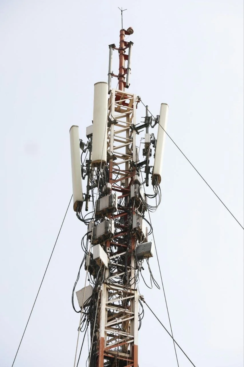
Telecom Towers Manufacturer UAE | Self-Supporting Lattice Communication Towers
ComTech Steel Industries manufactures heavy-duty telecom towers designed for high-capacity telecommunications installations requiring maximum equipment load capacity and height. Our self-supporting lattice towers provide robust infrastructure for multi-operator sites and high-density network deployments across the UAE and GCC region.
Telecom Towers Overview
Telecom towers are four-legged lattice structures offering superior load-bearing capacity compared to monopoles. These towers provide multiple mounting faces for extensive antenna arrays, making them ideal for sites requiring heavy equipment loads, multiple operator co-location, or heights exceeding practical monopole limits.
Our telecom towers are engineered using advanced structural analysis and manufactured to withstand extreme environmental conditions while supporting evolving technology requirements.
Design & Engineering Features
ComTech Steel Industries telecom towers incorporate heavy-duty engineering:
Height Range: 30 meters to 80 meters
Configuration: Four-legged self-supporting lattice
Base Width: 3 meters to 12 meters depending on height
Taper Design: Gradual reduction for structural efficiency
Multiple Mounting Faces: Four faces for equipment distribution
High Load Capacity: Supports extensive antenna arrays and equipment
Internal Climbing: Central ladder system for safe access
Platform Levels: Multiple working platforms at equipment zones
Wind Load Design: Engineered for up to 200 km/h wind speeds
Foundation System: Individual pier or combined mat foundation
Technical Standards & Compliance
Our telecom towers meet stringent international standards:
TIA-222-H: Telecommunications structure standards
AASHTO LTS-6: Structural design specifications
AWS D1.1: Welding quality requirements
EN 1461: Hot-dip galvanization standards
IEC 62305: Lightning protection systems
Seismic Design: Earthquake resistance where required
Service Life: 40-60 years with proper maintenance
Tower Configurations
Multiple structural configurations for different applications:
Standard Self-Supporting Tower
Four-Legged Design: Traditional lattice structure
Height Capability: Up to 80 meters
Equipment Capacity: Heavy load support
Base Area: Larger foundation footprint
Applications: Rural sites, high-capacity hubs
Reduced Footprint Tower
Optimized Base: Minimized ground area requirement
Height Range: 30-60 meters
Space Efficiency: Urban site compatibility
Load Capacity: Standard antenna arrays
Applications: Space-constrained locations
Heavy-Duty Hub Tower
Maximum Capacity: Extensive equipment support
Multiple Operators: 4-6 operator co-location
Height: 50-80 meters
Platform Levels: Multiple working platforms
Applications: Regional network hubs, backbone sites
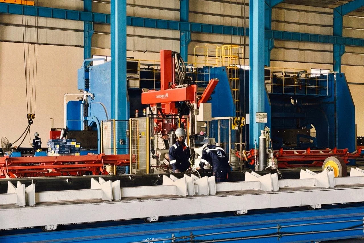
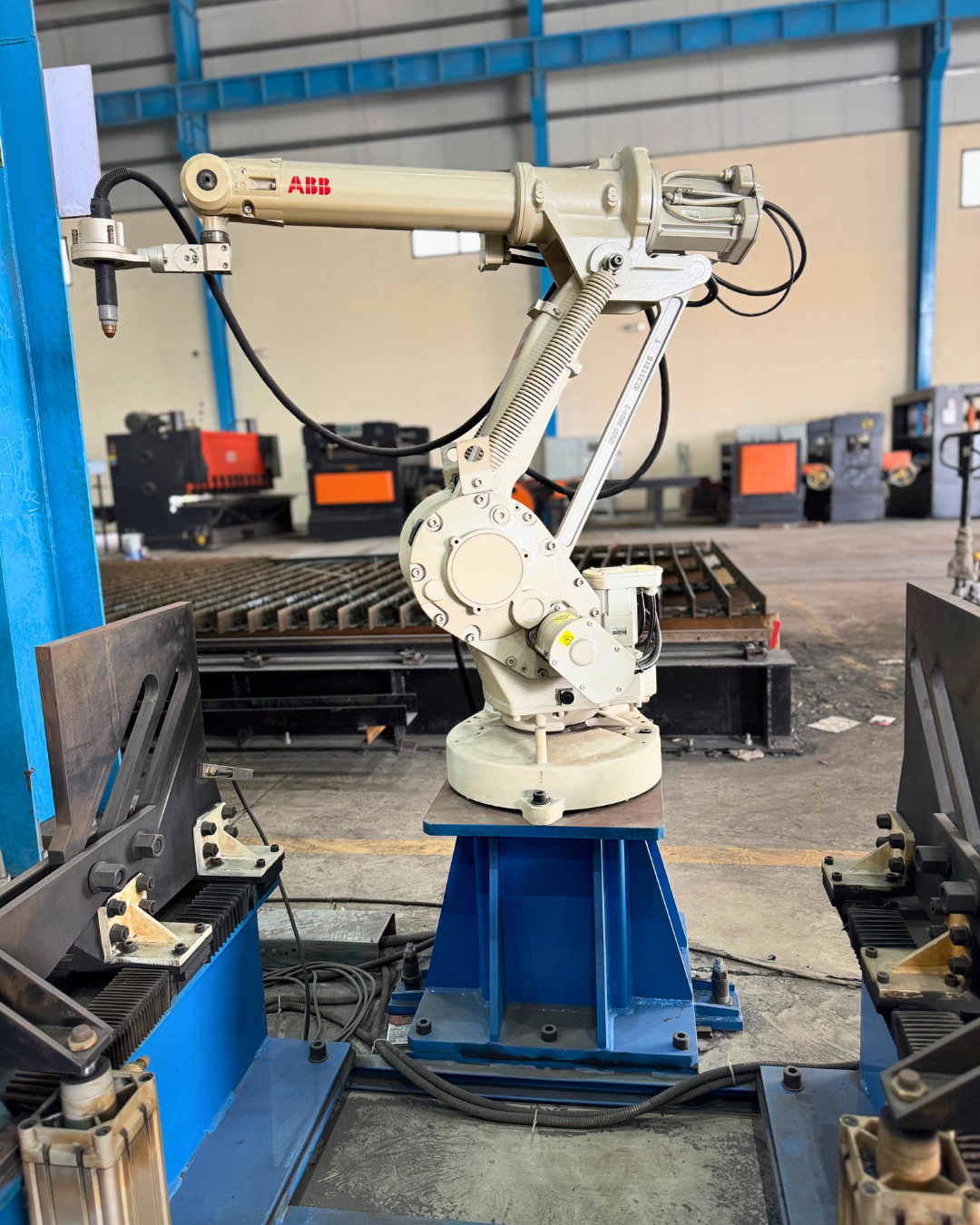
Manufacturing Process
Telecom towers undergo rigorous manufacturing:
Structural Engineering: Finite element analysis and optimization
Fabrication Drawings: Detailed member specifications
Member Fabrication: Angle sections cutting and preparation
Sub-Assembly: Panel and section assembly
Bolt Connections: High-strength bolted joints
Welding Operations: AWS D1.1 compliant welding
Hot-Dip Galvanization: Complete corrosion protection
Quality Inspection: Dimensional and coating verification
Packing & Shipping: Organized for efficient site assembly
Equipment Mounting Systems
Comprehensive mounting solutions:
Antenna Mounting
Four Mounting Faces: 360-degree equipment distribution
Sector Antennas: Multiple operators per face
Panel Arrays: High-capacity 5G installations
Microwave Dishes: Backhaul link support
Mounting Hardware: Adjustable brackets and pipe mounts
Cable Management: Ladder and tray systems
Equipment Platforms
Working Platforms: At each antenna level
Equipment Shelters: Platform-mounted cabinets
RRU Mounting: Proximity to antennas
Power Systems: Battery and rectifier platforms
Cable Distribution: Organized routing systems
Safety Features: Fall protection anchor points
Customization Options
Full customization for telecommunications requirements:
Custom Heights: 30m to 80m based on coverage needs
Base Dimensions: Optimized for site conditions
Load Capacity: Engineered for specific equipment
Platform Configuration: Custom levels and capacities
Access Systems: Internal ladder or service lift
Lightning Protection: Enhanced grounding systems
Aviation Marking: Lights and paint per regulations
Special Features: Microwave platform extensions
Applications
Telecom towers are essential for:
Regional Network Hubs: High-capacity aggregation sites
Rural Coverage: Long-distance signal propagation
Backbone Sites: Core network infrastructure
Multi-Operator Co-Location: Shared infrastructure sites
Microwave Backbone: Point-to-point radio networks
Emergency Services: Public safety communication networks
Border Coverage: International boundary connectivity
Industrial Complexes: Large facility coverage
Island Networks: Remote location connectivity
Military Communications: Defense infrastructure
Foundation Engineering
Custom foundation solutions for each site:
Soil Investigation: Comprehensive geotechnical analysis
Foundation Type: Pier, pad, or mat design
Anchor Bolt System: High-strength foundation anchoring
Load Transfer: Efficient structural load distribution
Settlement Analysis: Long-term stability verification
Seismic Considerations: Earthquake resistance where required
Construction Drawings: Complete foundation details
Installation Support
Complete tower erection assistance:
Erection Manual: Step-by-step assembly procedures
Crane Requirements: Lifting equipment specifications
Safety Procedures: Comprehensive safety protocols
Site Supervision: Engineering support available
Quality Assurance: Inspection during erection
Testing & Commissioning: Structural verification
As-Built Documentation: Complete site records
Maintenance & Inspection
Long-term structural integrity programs:
Periodic Inspection: Structural condition assessment
Bolt Torque Verification: Connection integrity checking
Coating Maintenance: Corrosion protection monitoring
Antenna Load Updates: Capacity verification for upgrades
Lightning Protection Testing: Grounding system verification
Structural Analysis: Re-analysis for technology changes
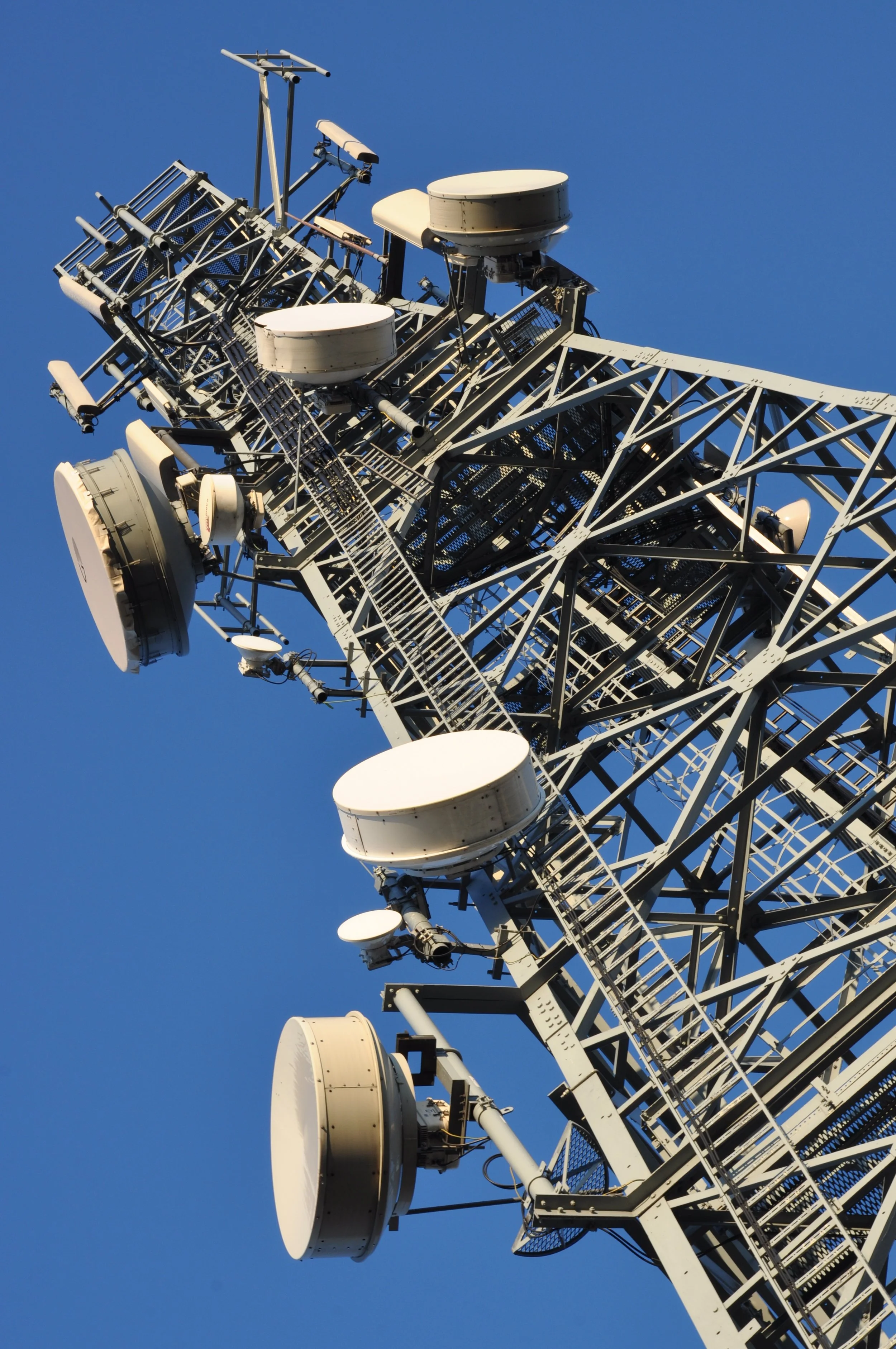
High-capacity steel towers designed to support heavy telecom equipment, antennas, and microwave links across large coverage areas.
Rooftop Masts Manufacturer UAE | Building-Mounted Telecom Structures
ComTech Steel Industries manufactures compact rooftop masts designed for telecommunications equipment installation on buildings where ground-level tower placement is impractical. Our rooftop masts provide cost-effective network deployment solutions for urban environments across the UAE and GCC region.
Rooftop Masts Overview
Rooftop masts are lightweight telecommunications structures specifically engineered for mounting on building rooftops, eliminating the need for ground-level tower sites. These masts offer height gain for improved coverage while minimizing visual impact and real estate requirements in dense urban environments.
Our rooftop masts are designed with careful consideration for building structural capacity, wind loads, and installation constraints typical of rooftop environments.
Design & Engineering Features
ComTech Steel Industries rooftop masts incorporate building-friendly engineering:
Height Range: 6 meters to 20 meters above roofline
Lightweight Construction: Minimized building load
Compact Footprint: Small rooftop area requirement
Multiple Configurations: Monopole, lattice, or guyed options
Equipment Capacity: Optimized for sector antenna arrays
Base Mounting: Ballasted, penetrating, or parapet-mounted
Wind Load Design: Building location wind analysis
Access Provisions: Safe rooftop access considerations
Cable Routing: From equipment room to antenna
Technical Standards & Compliance
Our rooftop masts meet telecommunications and building standards:
TIA-222-H: Telecommunications structure standards
Building Codes: Local structural requirements
AWS D1.1: Welding quality specifications
EN 1461: Hot-dip galvanization standards
Wind Load Analysis: Building-specific calculations
Seismic Considerations: Building movement accommodation
Service Life: 25-40 years
Mounting System Options
Multiple attachment methods for different buildings:
Ballasted Non-Penetrating Mount
No Roof Penetration: Preserves building warranty
Concrete Ballast: Secure weight-based mounting
Protective Pads: Roof membrane protection
Load Distribution: Spread footers reduce point loads
Flexibility: Easy relocation if needed
Applications: Flat roofs, membrane roofing
Penetrating Mount
Through-Roof Attachment: Secure structural connection
Flashing Integration: Waterproofing provisions
Load Transfer: Direct to building structure
Higher Capacity: Greater equipment loads supported
Permanent Installation: Long-term deployment
Applications: Reinforced concrete buildings
Parapet Mount
Wall Attachment: Mounts to existing parapet wall
Space Efficient: Minimal rooftop usage
Load Distribution: Through parapet to structure
Height Advantage: Additional elevation from parapet
Aesthetic: Less visible from ground level
Applications: Buildings with substantial parapets
Guyed Mast System
Maximum Height: Tallest rooftop option
Multiple Guy Anchors: Distributed load points
Equipment Capacity: Moderate antenna loads
Cost-Effective: Economical tall solution
Installation: More complex mounting
Applications: Large flat rooftops
Manufacturing Process
Rooftop masts undergo specialized manufacturing:
Building Assessment: Structural capacity evaluation
Custom Engineering: Building-specific load analysis
Mast Fabrication: Lightweight steel construction
Base Assembly: Mounting system preparation
Component Integration: Antenna brackets and cable management
Hot-Dip Galvanization: Corrosion protection
Quality Testing: Weight and dimension verification
Installation Kit: Complete hardware package
Documentation: Installation drawings and specifications
Customization Options
Full customization for building-specific requirements:
Height Selection: 6m to 20m based on coverage needs
Mast Type: Monopole, lattice, or guyed configuration
Mounting System: Ballasted, penetrating, or parapet
Equipment Capacity: Designed for antenna requirements
Surface Finish: Galvanized or powder coated
Color Matching: Building aesthetic coordination
Cable Management: Concealed routing solutions
Special Features: Stealth designs, concealment options
Applications
Rooftop masts are ideal for:
Urban Coverage: Dense city center deployments
In-Fill Sites: Coverage gap solutions
Shopping Centers: Mall and retail complex coverage
Office Buildings: Commercial building installations
Hospitals: Medical facility network coverage
Hotels: Hospitality wireless infrastructure
Parking Structures: Multi-level parking coverage
Industrial Buildings: Factory and warehouse rooftops
Residential Towers: Apartment building installations
5G Densification: Small cell deployment
Building Structural Considerations
Engineering for safe building integration:
Load Analysis: Dead load, wind load, seismic calculations
Structural Capacity: Existing building load verification
Reinforcement Requirements: Additional support if needed
Wind Uplift: Attachment adequacy verification
Vibration Analysis: Building response to mast
Foundation Investigation: Rooftop structural evaluation
Professional Engineer: Third-party verification available
Installation Procedures
Specialized rooftop deployment:
Crane Hoisting: Lifting to rooftop level
Assembly Methods: Rooftop or pre-assembly options
Anchor Installation: Mounting system securement
Waterproofing: Roof penetration sealing
Cable Routing: From equipment room to mast
Antenna Installation: Equipment mounting and alignment
Safety Measures: Fall protection and access
Inspection: Final structural verification
Advantages of Rooftop Deployment
Multiple benefits for network operators:
Reduced Costs: No ground lease requirements
Height Advantage: Elevation above surrounding buildings
Faster Deployment: Shorter approval processes
Space Efficiency: No ground area consumption
Urban Integration: Minimal visual impact
Equipment Access: Closer to existing facilities
Power Availability: Building electrical access
Security: Protected building rooftop location
Maintenance & Access
Long-term operational considerations:
Safe Access: Proper rooftop access provisions
Fall Protection: Anchor points and safety systems
Periodic Inspection: Structural and attachment verification
Antenna Maintenance: Equipment access procedures
Weatherproofing: Roof penetration monitoring
Coating Touch-Up: Corrosion protection maintenance
Compact steel masts designed for rooftop installations where ground space is limited, suitable for urban buildings and commercial properties.
Why Choose Telecom Infrastructure from ComTech Steel Industries

UAE-based manufacturing facility
Engineering-driven telecom structure design
Compliance with international telecom and structural standards
Custom solutions for site-specific requirements
Long service life and corrosion protection
Reliable production timelines and technical support
Request a Quote or Technical Consultation
Our engineering and sales teams are ready to support your telecom infrastructure project with technical guidance, design coordination, and customized manufacturing solutions.
Frequently Asked Questions
-
Yes. Height, configuration, load capacity, accessories, and finishes can all be customized to meet operator and site-specific requirements.
-
Our telecom infrastructure products comply with AASHTO, AWS D1.1, EN 1461, and relevant BS material and fabrication standards.
-
Lead time depends on design complexity, quantity, and customization level. Confirmed timelines are provided after technical review.
-
Yes. We provide technical drawings, documentation, and engineering support to assist with proper installation and deployment.
-
Our telecom structures are designed for a service life of approximately 25–50 years or more, depending on environmental conditions and coating systems.